iRoboBumper: SONAR-Obstacle Detection System for Robotics Platforms
Licensed under CC BY-SA 4.0
Hardware Design
The selection of the major components was discussed in the System Overview (see Section 2 of the Table of
Contents). These components must be integrated so that they function as a system. To do this, two Printed Circuit Cards (i.e.
PCBs) were designed and fabricated to help reduce the overall size of the system. The schematics, in PDF format,
and the gerber files that are
used to have PCBs manufactured are available for download from the Source Files section (see the Table of
Contents).
Now we will look at the design of each of the PCBs. The first PCB comprises the main system, and contains the voltage regulators, Arduino Pro
Mini socket, XBee module socket, temperature sensor, as well as connectors for the battery (i.e., J5, a 2 position 0.1”
(2.54mm) header), the PING))) sensors, rotation servo,
and proximity sensor. The second PCB just contains the
Vishay TCRT1010 Proximity Sensor and its associated circuitry. The proximity sensor was placed
on a separate PCB as it needs to be positioned so that it can detect holes in the non-rotating base of the
system. The position of each of these PCBs will be shown later when we discuss the mechanical part of the
system.
1. Main System PCB
We will start by looking at the Main System PCB schematic (also referred to as iRoboBumper Schematic), followed by a look at the schematic for the
Proximity/Optical Sensor PCB. After each
schematic has been discussed we will look at the PCB layouts and manufactured boards. The full schematic for the
Main PCB is shown in Figure 7.
Figure 7: iRoboBumper (Main System PCB) Schematic
2. Battery Input and Voltage Regulation
The circuitry required to connect everything together is not complicated but we will look at each section of the
schematic in detail to understand what is involved. The first section of the schematic is the battery input and
voltage regulation. This is located at the top of the full schematic and is shown in more detail in Figure 8.
Figure 8: Battery Connector and Voltage Regulators
The connection to the battery is made through a standard 2-pin, 0.1" pitch header. Two Low Drop-Out (LDO) voltage
regulators handle the generation of the 5 V and 3.3 V power required for the electronics. The 5-V regulator is a
Texas Instruments TPS76650, which can supply up to 250 mA of current. This is plenty of current for the
electronics that will be using the LDO (i.e. Arduino Pro Mini, PING))) sensors, and the temperature sensor)
since the steady state current draw, measured during prototyping of the system on a breadboard, was
approximately 100 mA.
The 3.3-V regulator is a Texas Instruments TPS77633D. This regulator is almost exclusively used by the XBee module and the current
capability of 500 mA was chosen because some XBee modules (i.e. WiFi) specify current draw during transmission
of up to 309 mA, and a current draw while receiving of approximately 100 mA. The ZigBee-based XBee ZB modules used in this project are much lower
power, with a specified maximum power draw of 45 mA and 40 mA, respectively, for transmit and receive modes. The
power draw of the XBee-PRO ZB modules (i.e. longer range modules) sit in between the WiFi and standard ZB module
at 205 mA and 47 mA for transmit and receive. This means our 3.3 Volt regulator should have the current capacity
for just about any standard XBee module, allowing flexibility for different wireless protocols to be used as
desired.
3. Interface for the Arduino Pro Mini Board
- Next, is the interface for the Arduino Pro Mini board. The Pro Mini has a standard form factor with two
12-pin, 0.1" through-hole headers that provides access to I/O and power signals. The pinout of these headers
are shown in Figure 9 below. This image nicely shows how all of the pins on the headers map to the Atmel
microcontroller's port pins, as well as how they map to the Arduino signals.
Figure 9: Arduino Pro Mini Pin Mapping. Source: http://www.pighixxx.com/test/portfolio-items/mini/?portfolioID=314
Figure 10 below shows what signals of the Arduino Pro Mini are used in our system.
Figure 10: Arduino Pro Mini Interface
- First, pins 1 and 2 are the transmit (TX) and receive (RX) serial lines that are used to communicate, via
the XBee module, with the host platform. These map to Arduino pins 1 and 0, respectively. Witness the value
in having a pin out diagram such as the one shown in Figure 9.
- Next, pins 5 and 6 (i.e., Arduino pins 2 and 3) are used to communicate with the PING))) sensors. These pins
were chosen because they are the external interrupt pins (i.e., INT0, and INT1). This will be discussed more
in the Software and
Configuration section,
but interrupts will be used to
calculate the duration of the pulse received from the PING))) sensors, which is then used to determine the
distance to a target object.
- Continuing with the Pro Mini interface, pin 12 (i.e., Arduino pin 9) is used to control the servo. This pin
was chosen since it is one of the pins capable of pulse width modulation (PWM) output.
- Finally, pins 15, 16, and 17 (i.e., Arduino pins 15/A1, 16/A2, and 17/A3) are used to read the analog
signals from the battery, proximity sensor and temperature sensor, respectively. The only other pins
connected on the headers are the 5-V power and ground pins.
4. Interface for the XBee Module from DIGI - (Figure 11)
- As with the Arduino Pro Mini, the XBee Module has a standardized pin out. However, this time the headers are
two 10-pin, 2mm pitch headers. The only signals we use on this module are pins 2 and 3 which are the TX and
RX serial interface for communication between the Arduino and XBee.
- Finally, we connect the 3.3-V and ground pins to power the module.
Figure 11: DIGI XBee Module Interface
The XBee is the only device in our system that is powered off of 3.3 V, but it has to communicate over the serial
port interface with the 5-V Arduino Pro Mini. This brings us to the Voltage Translator depicted in Figure 12.
The Texas Instruments’ PCA9306 is a 2-bit, bi-directional voltage
translator. It is primarily used as a voltage translator for I2C buses, where the data line switches
direction, but just as easily converts both of our signals (i.e., one driven from the 3.3-V side and the other
from the 5-V side).
Figure 12: Voltage Translator for Arduino / XBee
communication
5. Final Components on the Main System PCB - (Figure 13)
- The last components on the Main System PCB are the LMT87LP temperature sensor and a voltage divider that scales the
battery voltage to a range that can be read by the Arduino. In this case, the Arduino is using the regulated
5-V input as the reference, so we divide the voltage in half. Since we are running off of four AA batteries,
the supply voltage will be approximately 6 V, but could be up to approximately 7 V with a fresh set of
batteries. This should give us a scaled voltage of no more than about 3.5 V.
Figure 13: Temperature Sensor and Voltage Divider
- The tempSensor_out and scaled_vin signal are connected to the ADC3 and ADC1 pin on the Arduino Pro Mini,
respectively.
- Last, we have connectors to connect the two PING))) sensor modules, the servo, and the Vishay TCRT1010 Proximity Sensor board to the Main System PCB. These are all 3-pin 0.1"
pitch headers. They all supply power and ground, as well as a single signal that is connected to the Arduino
Pro Mini directly.
- In the case of the Proximity Sensor, the proximity_sig signal is connected to ADC2 as it is an analog
voltage. The ping1_sig and ping2_sig signals are connected to pins 5 and 6 (i.e. the 2 external interrupt
pins).
- Finally, the servo_control is connected to pin 12 of the Arduino Pro Mini which maps to Arduino pin 9 that
is capable of PWM output. These connector interfaces are shown in Figure 14 below.

Figure 14: Proximity, PING))) sensor, and Servo Interface
Connectors
6. Proximity/Optical Sensor PCB
Now, we will take a look at the Proximity/Optical Sensor PCB. This small board contains the TCRT1010 Proximity
Sensor and its associated electronics. This circuitry was placed on a separate board so that it could be placed
remotely from the rest of the system's electronics, as it will be placed facing down, through a hole, in the
base of the rotating part of the system to detect alignment holes in the non-rotating base. The full schematic for this board is shown in
Figure 15 below.
Figure 15: Proximity / Optical Sensor CCA from the Proximity /
Optical Sensor Schematic.
- As mentioned earlier, the TCRT1010 integrates an IR LED and photodiode into a single package and aligns them
to facilitate proximity detection. Simply put, the amount of current that passes through the photodiode will
increase/decrease as the amount of reflected IR energy from the IR LED increases/decreases. So as an object
comes closer to the device, it will reflect more of the IR LED's energy back to the photodiode, and less
energy as the object moves further away.
- Resistor R3 is used to control/limit the current through the IR LED and thus determines how much energy it
emits. From the TCRT1010's datasheet, it was
determined to design the circuit to limit this current to approximately 25 mA. Using the 5 V input and 1.25
V typical voltage drop of the IR LED, the voltage across the resistor will be approximately 3.75 V. Thus,
the 150 ohm resistor should set the current at approximately 25 mA.
- Resistor R4 is used to convert the current flowing through the photodiode to a voltage, which will increase
and decrease as the amount of IR energy being received by the photodiode increases and decreases. This
voltage is what will be read by the Arduino Pro Mini’s analog-to-digital convertor (ADC) and thus to detect
the presence or absence of an alignment hole.
- However, when the TCRT1010 was placed on a breadboard, the voltage level across R4 was relatively small
compared to the 5 V reference voltage of the Arduino’s ADC. For example, the maximum output voltage was
about 1.5 V when a very reflective object was placed very close (~2mm) to the device.
- Thus, an op amp is used to allow this output voltage to be scaled up to occupy more of the 5 V dynamic
range of the ADC of the Arduino Pro Mini.
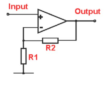
- Resistors R1 and R2 set the gain of the non-inverting amplifier stage using the standard equation: Gain = 1 +
(R2/R1). Since both R1 and R2 are 1 kOhms, the gain of this amplifier stage is approximately 2.
- Finally, since the output is being driven over a cable and this board could potentially be reused in
other projects, a second op amp is used as a unity gain buffer to prevent the load of the cable and
external circuitry from affecting the gain of the first stage (i.e., U2.2 in Figure 15).
7. PCB Layouts and Component Population of Main System Board and Proximity/Optical Sensor Board
- Both PCB’s are fairly simple 2-layer PCBs and should be producible by just about any PCB manufacturer.
Figure 16 below shows the top and bottom side of each PCB design.
Figure 16: Board Layouts for Both PCBs
- Once the PCBs were designed, they were ordered from OSH Park
(http://oshpark.com/) for manufacturing. OSH Park allows small orders (2 and 4 layer PCBs) at
affordable prices. Their boards are high quality and have ENIG (gold) finished pads. There are also solder
masks and silkscreening on both sides. The solder mask color used by OSH Park is a dark purple that is
recognizable by many hobbyists.
- A reflow oven was used to solder
all of the surface mount parts, so solder paste stencils were also ordered from OSH Stencils (http://oshstencils.com) for both PCBs.
These are inexpensive stencils made from polyimide. You can order 3-mm or 5-mm thick stencils. Figure 17 below shows images
of the unpopulated PCBs and stencils.
Figure 17: Unpopulated PCBs and Stencils Source: Author.
- Next, a reflow oven was used to populate the surface mount parts with the help of the stencils and solder
paste, followed by hand soldering for the through-hole connectors and parts. Figure 18 below shows both PCBs
after all parts and connectors have been populated.
Figure 18: Populated PCB Images. Source: Author.
Now that we have fully populated PCBs, we will look at the mechanical design of the
system.
We would love to hear what you think about this project; please tell us in the
comments section below.


